Building a Mold using a 7T MRI scan of the MTL
About this Protocol
Use this protocol when you have scanned the entire MTL specimen on a 7T MRI scanner. The 7T MRI introduces minimal distortion to the tissue and can be used directly for mold generation. By contrast, the animal 9.4T scaner introduces distortions that have to be corrected by registration to a 7T scan first.
Step 1. Download Input MRI Scan
Create a new folder for each mold-making project. All files should be saved in this folder.
The required input to this protocol is a 7T MRI scan of the MTL. It should be converted to the NiFTI file format and saved as mtl7t.nii.gz
When selecting the 7T scan, do not use the scan with the
_ndin its name. Those images are saved without on-the-scanner distortion correction and are not suitable for mold making.
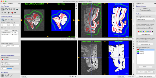
Step 2. Segment the MTL from the Background in ITK-SNAP
Load
mtl7t.nii.gzinto ITK-SNAPEnter the automatic (snake) segmentation mode
Enter “classification” pre-segmentation mode
Label the tissue as “red” label, and background (fomblin) as “green” label
If there is some water on top of the sample, label it with another label
Under “More…” set the “Neighborhood size” to 2
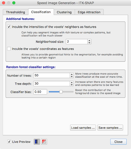
Click “Train Classifier” to isolate foreground from background
Repeat this process (adding training samples where the classifier messes up and retraining classifier) until satisfied with the pre-segmentation.
Under “More…”, save the classifier training samples as
training_samples.nii.gzClick “Next” to enter bubble placement mode
Move your cursor around the sample and click Add Bubble at Cursor to place bubbles.
Click Next again and run contour (snake) evolution by clicking the play button. Verify that the segmentation is good. Do not press Finish yet.
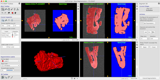
Before clicking Finish, open the layer inspector window (Tools -> Layer Inspector…) and save the evolving contour layer as
contour_image.nii.gz.Exit the segmentation mode. You do not need to save the actual segmentation
Step 3. Create a Reference Mold
Open a terminal window. Make sure that the directory containing
mold_helper.shis in your PATH. You can do this by typing:PATH=/home/user/.../path/to/mold_helper:$PATH export PATH
Change directory to the folder containing your files:
cd /home/user/.../workdirCreate a reference mold by typing this command. The value 0.4 is the spacing between cutting slits in mm. It may be adjusted if the slits are too narrow.
mold_helper.sh make_reference_mold 0.4Running this command will generate an image
reference_mold.nii.gzin your working folder. Open this image in ITK-SNAP.
Step 4. Position the Specimen in the Mold
In this step, we align the sample in the mold optimally. Optimal alignment takes into account several factors:
The specimen should lie inside the reference mold, with no portion below the “solid” bottom of the mold, and as little as possible protruding
The part of the specimen coming into contact with the 3D print should be least valuable - i.e., sides of the specimen where it was cut, as opposed to pial surface.
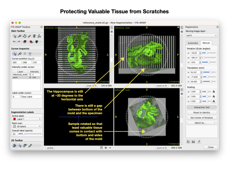
The specimen should be approximately aligned with the AC/PC axis when sectioned - this means the hippocampus is at about 20 degree angle to the longitudinal axis of the mold
The cross-section of the specimen along the cutting direction should fit onto 75x50mm slides. Satidfying this condition may require you to override with the ACPC rule above.
Load
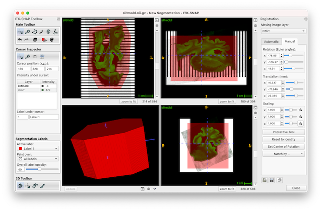
reference_mold.nii.gzas the main image in ITK-SNAPLoad
mtl7t.nii.gz`as the overlay image using File->Add Another Image. When prompted, select “As a semi-transparent overlay” option.Enter registration mode (Tools->Registration) and go to the “Manual” tab
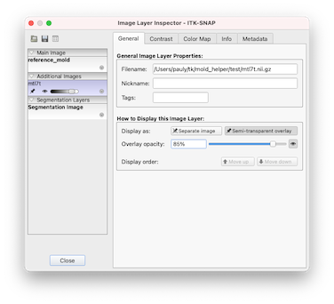
Display the MRI scan as a semi-opaque overlay (if not already displayed this way):
Tools->Layer Inspector
Select the MRI layer
Go to the General tab
Click Display as semi-transparent overlay and set opacity to 85%
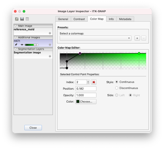
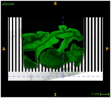
You can play with the color map (Tools->Layer Inspector, “Color Map” tab) to get a better transparency display, allowing you to see both the mold and the tissue well. Here we used the Black to Green color map and played with the control points to get a nice overlay visualization.
Initially align the MRI to the mold by selecting Match By…->Image Centers on the ITK-SNAP registration panel. Then use the wheel to rotate the specimen, and drag away from the wheel to move the sample.
Rotate and move the MRI so that the sample is in approximate AC/PC alignment.
The tissue should be inside the “slitted” region of the reference mold. In other words, the bottom of the tissue should be above the line where the slits begin.
The tissue should be approximately centered in the mold on the L-R axis and A-P axis.
Orient the tissue as in an in vivo MRI scan, bottom of the brain to the bottom of the screen, as shown below. Focus on rotating the sample in the top right window so that the hippocammpus is curving up at about 20 degree angle, and so that the posterior edge of the specimen is approximately parallel to the slits. This assumes that the posterior edge was cut approximately perpendicular to the AC/PC line.
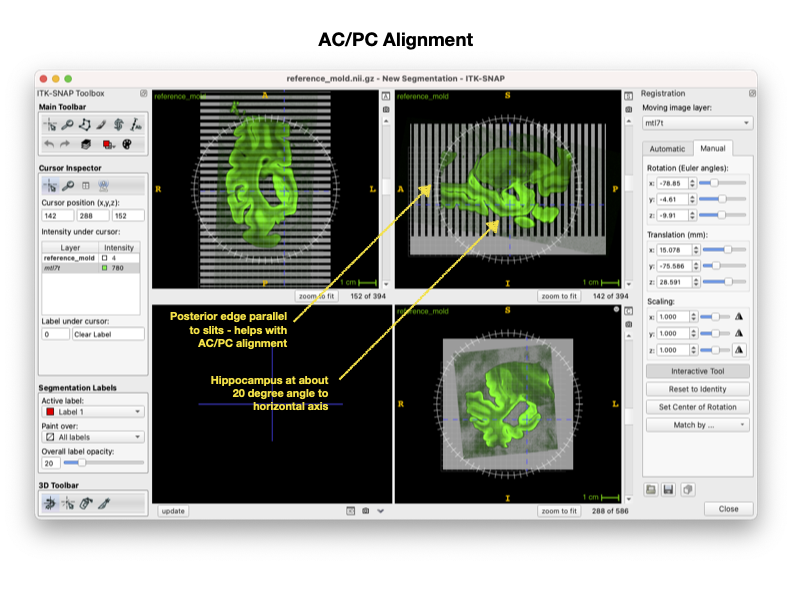
Rotate and move the MRI so that the valuable tissue does not get scratched when placing the sample in the mold. At this point, you should be rotating only in the bottom right window. This keeps the AC/PC alignment even as you rotate the sample.
As before, the tissue should be inside the “slitted” region of the reference mold. In other words, the bottom of the tissue should be above the line where the slits begin.
Medial temporal lobe should be facing up or in such a way that when the sample is lowered into the mold, the MTL and as much of the rest of the temporal lobe cortex does not touch the sides or bottom of the mold.
Carefully scan through the length of the mold in the coronal (bottom right) view and check the following:
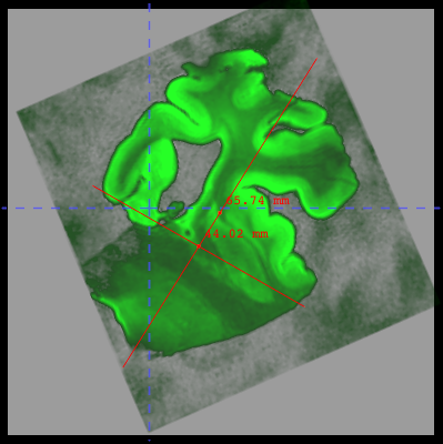
Find a slice in the MRI where the tissue looks to be the largest, and measure the tissue to ensure that the largest portions of the tissue would fit on a 75mm x 50mm glass slide (2”x3” slide). If not, try rotating the sample slightly in the sagittal (top right) view
Make sure the sample is inside of the slitted region.
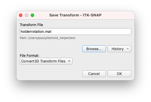
When satisfied, use the small floppy disk icon in the bottom right of the registration panel above close to save your registration as holderrotation.mat
Save your workspace (Workspace->Save Workspace) as
INDD123456_mold7t.itksnap
Step 5. Carve the tissue segmentation out of the mold
This command carves out the tissue segmentation out of the mold. It generates an image that is positive inside the plastic mold and negative in the air.
mold_helper.sh carve_mold
Step 6. Trim the mold to reduce plastic use
Open
slitmold.nii.gzin a new ITK-SNAP windowLoad
mtl7t.nii.gzas an additional imageEnter registration mode and use the open icon to load
holderrotation.matDraw the trimming polygon at the top of the sample: * Use the Crosshairs tool to position the cursor slightly superior to the top of the sample * Use the Polygon tool and draw around the tissue but leaving out excess plastic, like shown below. Try to not leave any very thin slivers of plastic as you do this - position the vertices of the polygon inside of the slits. * Once polygon is drawn (you can edit the individual vertices), click accept
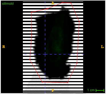
Draw the trimming polygon at the bottom of the sample: * Use Crosshairs tool again to position the cursor (same horizontal blue line) about 5mm below the bottom of the slits. This will result in less plastic at the bottom of the mold.
Click the Polygon tool again, then click paste last polygon to draw the identical polygon in that slice.
Click accept again
Interpolate between these polygons using Tools->Interpolate Labels
Save the segmentation as
cropmask.nii.gzRun the following command to crop the block:
mold_helper.sh finish_mold
This should generate files
slitmold.stlandsample_inplace_mesh.stl. These files are huge and need to be simplified before 3D printing.
Step 7. Process meshes in MeshLab
You need to download MeshLab for this step.
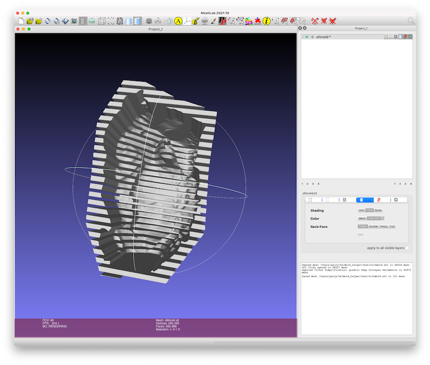
Run Meshlab and load
slitmold.stlusing File->Import MeshGo to Filters->Remeshing->Quadric Edge Collapse Decimation and set options as recommended below: * Percentage reduction: 0.1 * Preserve boundary: checked * Preserve normal: checked * Preserve topology: checked * Optimal position: checked * Planar simplification: checked * Post-simplification: checked * Hit Apply. It may take a few minutes.
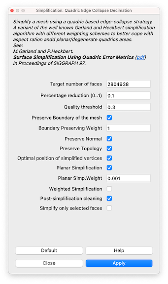
The simplified mesh should be visually similar to the input mesh, but will have 90% fewer faces.
Save mesh (using File->Export Mesh…), overriding the existing very large mesh.
Repeat the same process for
sample_inplace_mesh.stl, however: * After loading the mesh, the shading will be wrong. Select Filters->Normals, Curvatures and Orientation->Invert Faces Orientation and run that filter after loading the mesh.
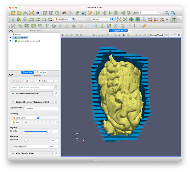
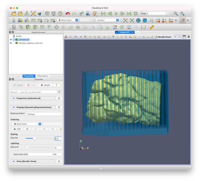
Step 8. Visualize sample placement in mold
Open the meshes
slitmold.stlandsample_inplace_mesh.stlin ParaView.Adjust the color and transparency of the meshes for good visualization
Take screenshots from a few angles